Today (Saturday 19th October 2024) the 1st Ashley Air Scouts had a very successful JOTA (Jamboree On The Air) from Hugo Meynell school in Loggerheads with help from the Staffordshire and District Amateur Radio Society along with myself.
My main role today was educational, to teach the Scouts, Cubs and Beavers some of the phonetic alphabet and explain why we use call signs to identify stations and why we speak the call signs in the phonetic alphabet they have just learned due to poor operating conditions. Some already knew their phonetic alphabet, and as one young cub pointed out, I didn’t even know the normal alphabet..! I was just testing them, or rather, that was my excuse. LOL
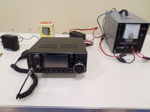
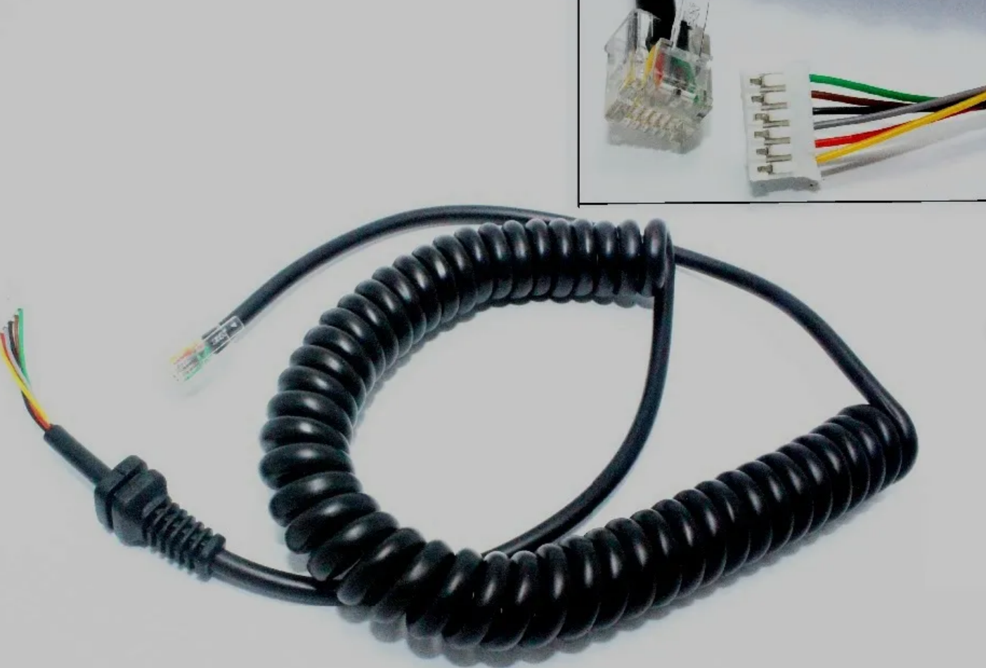
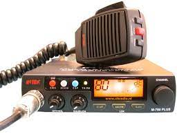
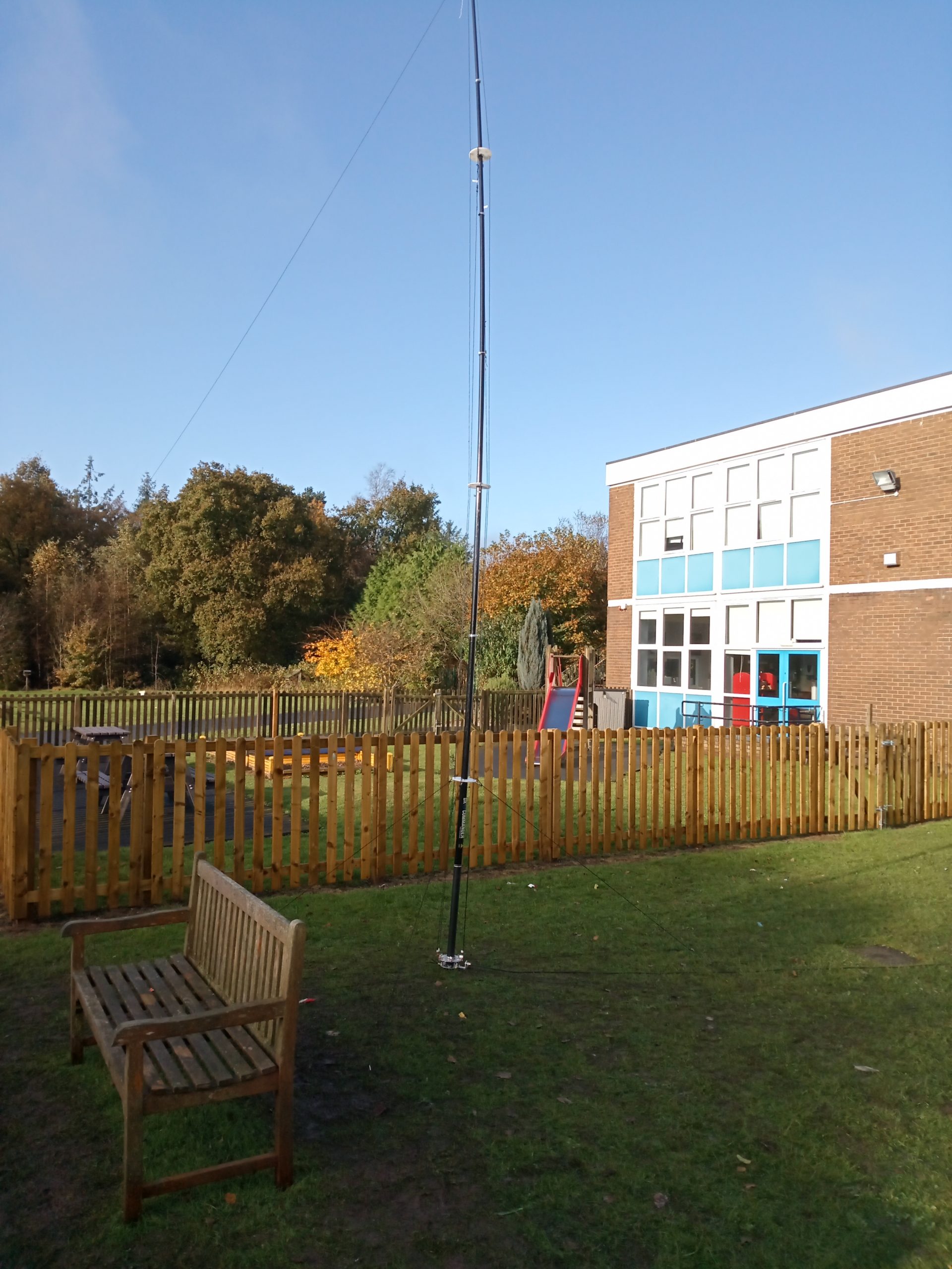
After their lesson, they were let on to the club’s HF station, an Icom 7300 connected to a DX-Commander operated by Paul, and with his assistance, contact was made with other JOTA stations, and very basic messages were exchanged, like names and with what they had just learned, the spelling of their names phonetically.
Between 10:30 and 15:00, I believe contacts were made in York, Hebden Bridge, Jersey, Germany, Italy, Poland, Russia, Indonesia, Ireland, Japan, Vietnam, Mauritius and Taiwan.
The conditions of the bands were very noisy, 40m being the worse, so in the late morning, I got the impression that everyone was crowding on 20m in order to make a JOTA contact. In the afternoon, the 40m band picked up again, but, signals seemed distant, quiet, and faded in and out. A very difficult band to work today.
Due to these really difficult working conditions, GB1SDS did try listening out for GB4FAS (operated by my radio club The West Manchester Radio Club), but, despite trying, GB1SDS simply could not hear GB4FAS 70 miles away.
Overall, a very busy and fulfilling day, I would definitely do it again.
I would like to say a big thank you to the members of the Staffordshire and District Radio Society for their assistance in helping this local scout group do this and the troop gain their JOTA badges.